Interfacing Servo Motor with Arduino Nano – Complete Guide with Code
Table of Contents
Abstract
Servo motors are precise, compact actuators widely used in robotics, automation, and DIY electronics projects. In this tutorial, you will learn how to interface a standard SG90/MG996R servo motor with an Arduino Nano using the Arduino IDE and the built-in Servo.h library. By the end, you will be able to control servo angle programmatically, create smooth motion sequences, and integrate servos into your own embedded projects.
 Pre-Request
- OS : Windows / Linux / Mac / Chrome
- Arduino IDE
Hardware Required
Arduino boards, sensors, and maker essential Kits—perfectly matched for your learning.
- Arduino Nano.
- Servo Motor (SG90)
- BreadBoard.
- Mini USB Cable.
- Connecting wires.
- 5V DC power supply (Optional)
| Components | Purchase Link |
|---|---|
| Arduino Nano | link |
| Servo Motor (SG90) | link |
| Mini USB Cable | link |
| BreadBoard | large : small |
| Connecting Wires | link |
| 5V DC Adaptor | link |
Don't own a hardware 
No worries,
💡Still you can learn using simulation. check out simulation part  .
.
💡Power your mission with reliable Arduino Kits. Explore Hardware →


⚡ Understanding Servo Motors (PWM Control)
A servo motor is a closed-loop actuator that uses PWM (Pulse Width Modulation) signals to control angular position precisely between 0° to 180° (standard servos) or 0° to 270° (continuous rotation variants).
📌 Why Use Servo with Arduino Nano?
- Precise angular control 🎯
- Simple 3-wire interface 🔌
- Built-in Arduino
Servo.hlibrary support 📚 - Ideal for robotic arms, camera gimbals, valve control 🤖
- Low cost and beginner friendly 💡
📌 How PWM Controls Servo Angle:
| Pulse Width | Approximate Angle |
|---|---|
| 1000 µs | 0° |
| 1500 µs | 90° (Neutral) |
| 2000 µs | 180° |
Arduino's Servo library abstracts PWM timing, letting you control angle directly with servo.write(angle).
🧷 Connection / Wiring Guide (Arduino Nano to Servo)
Servo motors have 3 wires:
- 🔴 Red → VCC (5V)
- 🟤 Brown/Black → GND
- 🟡 Orange/Yellow → Signal (PWM Pin)
🔥 Arduino Nano to Servo Pin Mapping
| Servo Wire | Arduino Nano Pin | Description |
|---|---|---|
| Red (VCC) | 5V (or External 5V) | Power supply |
| Brown (GND) | GND | Common ground |
| Orange (Signal) | D3, D5, D6, D9, D10, D11 | PWM-capable digital pin |
Power Consideration
Arduino Nano's 5V pin can supply ~500mA max. SG90 draws ~100-250mA (safe). MG996R can draw >1A under load — use external 5V supply and connect GNDs together.
Info
Use PWM-capable pins (~) for servo signal. Arduino Nano PWM pins: D3, D5, D6, D9, D10, D11. Pin D9 is used in this example.
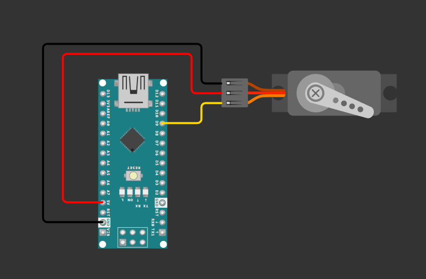
fig-Connection Diagram
 Code
Code
Info
Install Servo Library from Arduino Library Manager.
🧠 Code Explanation
Let's break down the code section by section.
 Include Servo Library
- Imports Arduino's built-in
Servolibrary for PWM-based servo control. - Handles timing and pulse generation automatically.
Configuration Macros
#define SERVO_PIN     9
#define MIN_ANGLE     0
#define MAX_ANGLE     180
#define STEP_DELAY    1000
#define STEP_ANGLE    10
| Macro | Purpose |
|---|---|
SERVO_PIN |
Digital PWM pin connected to servo signal wire |
MIN_ANGLE / MAX_ANGLE |
Defines servo rotation range |
STEP_DELAY |
Controls sweep speed (higher = slower motion) |
STEP_ANGLE |
Defines sweep angle |
Servo Object Declaration
- Creates an instance of the
Servoclass namedmyServo. - This object provides methods like
.attach(),.write(),.detach().
Setup Function
| Function | Description |
|---|---|
Serial.begin(9600) |
Initializes serial communication for debugging output |
myServo.attach(pin) |
Binds servo object to hardware PWM pin |
myServo.write(90) |
Moves servo to neutral (90°) position at startup |
delay(500) |
Allows mechanical settling time |
Loop Function - Angle Sweeping
for (int angle = MIN_ANGLE; angle <= MAX_ANGLE; angle = angle + STEP_ANGLE) {
  myServo.write(angle);
  Serial.print("Angle: ");
  Serial.println(angle);
  delay(STEP_DELAY);
}
- Iterates angle from 0° → 180° (forward sweep with STEP_ANGLE)
myServo.write(angle): Sends appropriate PWM signal for target angleSerial.println(): Outputs current angle to Serial Monitordelay(): Controls motion smoothness and speed
Warning
Rapid angle changes or mechanical obstruction can cause servo jitter, gear stripping, or overheating. Always test with conservative delays first.
Simulation
Not able to view the simulation
- Desktop or Laptop : Reload this page ( Ctrl+R )
- Mobile : Use Landscape Mode and reload the page
Arduino boards, sensors, and maker essential Kits—perfectly matched for your learning.
🛑 Troubleshooting (Common Issues & Fixes)
❌ Issue 1: Servo Jitters or Doesn't Move
✅ Possible Causes: - Insufficient power supply from Arduino 5V pin - Loose or disconnected signal wire - Using non-PWM pin for servo signal
✅ Solutions: - Use external 5V/2A power supply for high-torque servos - Ensure GND is common between Arduino and external power supply - Verify signal wire connects to PWM-capable pin: D3, D5, D6, D9, D10, D11
❌ Issue 2: Servo Moves Erratically or Arduino Resets
✅ Possible Causes: - Voltage drop under servo load causing brownout - Electrical noise coupling into signal line
✅ Solutions: - Add 100µF–470µF electrolytic capacitor across servo VCC-GND - Use separate regulated 5V supply with common ground - Keep servo wires short and routed away from high-current paths - Add ferrite bead on servo power line if noise persists
❌ Issue 3: Angle Range Incorrect (e.g., only moves 0-90°)
✅ Possible Causes: - Servo mechanical stop variation between units - Library default pulse width doesn't match servo specifications
✅ Solutions:
- Calibrate using attach(pin, min, max) with custom pulse widths:
writeMicroseconds() to find actual servo limits
Extras
Components details
🏗️ Project Extensions / Next Steps
🔧 Ideas to Expand This Project:
-
Potentiometer-Controlled Servo
Map analog input (0-1023) to servo angle (0-180°) for manual positioning interface. -
Ultrasonic Radar Scanner
Mount HC-SR04 ultrasonic sensor on servo to create a 180° distance-mapping radar display. -
Bluetooth Servo Control
Integrate HC-05/HC-06 Bluetooth module to control servo angle via smartphone app. -
Multi-Servo Robotic Arm
Combine 3-4 servos with basic inverse kinematics for pick-and-place automation. -
Web-Controlled Servo via ESP-01
Bridge Arduino Nano with ESP8266 for IoT-based remote servo actuation over WiFi. -
Joystick Dual-Axis Control
Use analog joystick to control two servos simultaneously for pan-tilt camera mount.
Conclusion
Interfacing a servo motor with Arduino Nano is a foundational skill for robotics, automation, and interactive electronics projects. By leveraging Arduino's built-in Servo.h library, you can achieve precise angular control with minimal code and hardware complexity.
Using Wokwi simulation, students and developers can test designs before building physical circuits, making this project perfect for learning and prototyping.
🚀 Next Step: Combine this servo control with sensor input (potentiometer, ultrasonic, IMU, or Bluetooth) to create interactive, real-world embedded projects!