KY-023 Joystick + Arduino Uno: Wiring, Code & Calibration for Beginners
Table of Contents
Abstract
Joystick modules are versatile input devices widely used in robotics, gaming controllers, RC vehicles, and human-machine interfaces due to their intuitive two-axis control and built-in push-button functionality. In this tutorial, you will learn how to interface a standard KY-023 dual-axis joystick module with an Arduino Uno microcontroller using the Arduino Framework. By the end, you will be able to read analog X/Y axis values, detect button presses, calibrate joystick centering, and integrate joystick input into your own embedded projects with confidence.
Pre-Request
- OS: Windows / Linux / macOS
- Arduino IDE (v2.x recommended) or Arduino Web Editor
- Arduino Uno with CH340/FTDI drivers installed
- USB Cable (Mini-B for classic Uno, USB-C for newer variants)
- Basic understanding of C++ syntax and Arduino programming concepts
Hardware Required
Arduino boards, sensors, and maker essential Kits—perfectly matched for your learning.
- Arduino Uno (ATmega328P)
- KY-023 Dual-Axis Joystick Module
- Breadboard (mini or full-size)
- USB Mini-B Cable
- Jumper wires (M-M and M-F)
- Optional: 5V external power supply for high-current projects
| Components | Purchase Link |
|---|---|
| Arduino Uno | link |
| KY-023 Joystick Module | link |
| Mini USB Cable | link |
| BreadBoard | large : small |
| Connecting Wires | link |
| 5V DC Adaptor | link |
Don't own a hardware 
No worries,
💡Still you can learn using simulation. check out simulation part  .
.
💡Power your mission with reliable Arduino Kits. Explore Hardware →


🔋 Power Note
The KY-023 joystick operates at 3.3V–5V and draws minimal current (<10mA), so it can be safely powered from the Arduino Uno's 5V pin.
⚡ Understanding Joystick Module & Analog Input
The KY-023 is a popular analog joystick module featuring two potentiometers (for X and Y axes) and a tactile push-button switch. Unlike digital buttons, joysticks output variable analog voltages proportional to their position, which the Arduino reads via its Analog-to-Digital Converter (ADC).
🔹 How Analog Joystick Works
| Joystick Position | X-Axis Voltage | Y-Axis Voltage | ADC Value (0–1023) |
|---|---|---|---|
| Center (Neutral) | ~2.5V | ~2.5V | ~512 |
| Full Left | ~0V | ~2.5V | ~0 (X), ~512 (Y) |
| Full Right | ~5V | ~2.5V | ~1023 (X), ~512 (Y) |
| Full Up | ~2.5V | ~0V | ~512 (X), ~0 (Y) |
| Full Down | ~2.5V | ~5V | ~512 (X), ~1023 (Y) |
ADC Resolution & Mapping
Arduino Uno features a 10-bit ADC (0–1023 range) across 0–5V input. The analogRead() function converts analog voltage to digital values:
Button Switch Logic
The built-in push-button is active-LOW:
- Not pressed: Output = HIGH (5V via pull-up)
- Pressed: Output = LOW (0V, connected to GND)
🧷 Connection / Wiring Guide (Arduino Uno to Joystick Module)
🔥 Pin Mapping Table
| Joystick Pin | Label | Arduino Uno Pin | Description |
|---|---|---|---|
| GND | GND | GND |
Common ground reference |
| +5V | VCC | 5V |
Power supply (3.3V–5V compatible) |
| VRx | X-Axis | A0 |
Analog output for horizontal movement |
| VRy | Y-Axis | A1 |
Analog output for vertical movement |
| SW | Button | D2 |
Digital output for push-button (with INPUT_PULLUP) |
⚠️ Important
Always connect GND first to avoid floating inputs and erratic readings.
Wiring Diagram

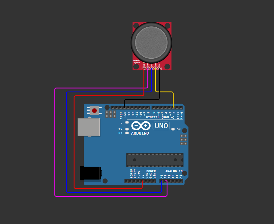
fig-Connection Diagram
💡 Pro Tip
Use the Arduino Uno's A6 and A7 for additional analog inputs if needed—they are analog-only pins (no digital functionality).
 Code
Code
// Pin Definitions
const int PIN_X = A0;        // X-axis analog input
const int PIN_Y = A1;        // Y-axis analog input
const int PIN_BTN = 2;       // Button digital input

// Calibration values (adjust for your module)
const int CENTER_THRESHOLD = 20;  // Deadzone around center
const int MIN_VAL = 0;
const int MAX_VAL = 1023;
const int CENTER_VAL = 512;

void setup() {
  // Initialize Serial communication
  Serial.begin(9600);
  while (!Serial); // Wait for Serial Monitor

  // Configure button pin with internal pull-up
  pinMode(PIN_BTN, INPUT_PULLUP);

  Serial.println("🎮 Joystick Initialized");
  Serial.println("X\tY\tButton");
  Serial.println("--------------------");
}

void loop() {
  // Read analog values (0-1023)
  int xValue = analogRead(PIN_X);
  int yValue = analogRead(PIN_Y);

  // Read button state (LOW = pressed)
  bool buttonPressed = (digitalRead(PIN_BTN) == LOW);

  // Optional: Apply deadzone filtering for center position
  if (abs(xValue - CENTER_VAL) < CENTER_THRESHOLD) xValue = CENTER_VAL;
  if (abs(yValue - CENTER_VAL) < CENTER_THRESHOLD) yValue = CENTER_VAL;

  // Output to Serial Monitor
  Serial.print(xValue);
  Serial.print("\t");
  Serial.print(yValue);
  Serial.print("\t");
  Serial.println(buttonPressed ? "PRESSED" : "RELEASED");

  // Small delay for stable readings
  delay(100);
}
Code Explanation
 Pin Definitions & Constants
- Defines Arduino pins connected to joystick module
A0/A1are analog input pins;D2is digital for button
Calibration Parameters
CENTER_THRESHOLD: Deadzone radius to ignore minor drift at neutral positionCENTER_VAL: Expected ADC value at joystick center (~512 for 10-bit ADC)
Setup Function
- Initializes serial communication at 9600 baud
- Configures button pin with internal pull-up resistor (no external resistor needed)
Main Loop: Reading & Filtering
int xValue = analogRead(PIN_X);
int yValue = analogRead(PIN_Y);
bool buttonPressed = (digitalRead(PIN_BTN) == LOW);
- Reads raw analog values for X/Y axes (0–1023)
- Reads button state (active-LOW logic)
Deadzone Filtering (Optional but Recommended)
- Prevents "jitter" when joystick is near center by snapping values to neutral
- Adjust
CENTER_THRESHOLD(10–30) based on your module's precision
Serial Output
- Outputs tab-separated values for easy parsing or Serial Plotter visualization
- Use Tools > Serial Plotter in Arduino IDE for real-time graphing
Simulation
Not able to view the simulation
- Desktop or Laptop : Reload this page ( Ctrl+R )
- Mobile : Use Landscape Mode and reload the page
Arduino boards, sensors, and maker essential Kits—perfectly matched for your learning.
🛑 Troubleshooting (Common Issues & Fixes)
❌ Issue 1: Joystick values stuck at 0 or 1023
✅ Causes: - Loose/broken jumper wires - Incorrect pin connections (VRx to digital pin) - Module powered with wrong voltage
✅ Fix:
// Verify connections with a simple test
void setup() {
  Serial.begin(9600);
}
void loop() {
  Serial.println(analogRead(A0)); // Should vary 0-1023 when moving joystick
  delay(200);
}
❌ Issue 2: Joystick drifts or doesn't return to center
✅ Cause: - Mechanical wear or low-quality potentiometer - ADC noise without filtering
✅ Fix:
// Implement software deadzone (already in main code)
if (abs(xValue - 512) < 25) xValue = 512;

// Optional: Add simple moving average filter
int readFiltered(int pin, int samples = 5) {
  long sum = 0;
  for(int i=0; i<samples; i++) sum += analogRead(pin);
  return sum / samples;
}
CENTER_VAL for your specific module (print raw values at rest)
- Add 0.1µF capacitor between VRx/VRy and GND for noise reduction
❌ Issue 3: Button always reads as pressed
✅ Cause:
- Missing INPUT_PULLUP configuration
- Short circuit on SW pin
✅ Fix:
- Verify button wiring: SW → D2, no external resistor needed - Test with multimeter: SW pin should read ~5V (not pressed) / 0V (pressed)❌ Issue 4: Serial Monitor shows garbled text
✅ Cause: - Baud rate mismatch between code and Serial Monitor - USB communication issues
✅ Fix:
- Ensure Serial.begin(9600) matches Serial Monitor dropdown selection
- Try different USB cable or port
- Reset Arduino Uno after uploading code
🏁 Conclusion
You have successfully interfaced a KY-023 joystick module with an Arduino Uno using the Arduino Framework 🎉. You now understand:
- How analog potentiometers generate variable voltage signals for position sensing
- How to read and calibrate ADC values for reliable input detection
- Best practices for button debouncing, deadzone filtering, and noise reduction
- Techniques for debugging and validating sensor connections
With this foundation, you can build interactive projects like: - 🤖 RC robot directional control - 🎮 Custom game controller interfaces - 🎚️ Pan-tilt camera positioners - 🖱️ DIY mouse/trackball alternatives - 🎛️ Menu navigation systems for OLED displays
Next Steps
- Map joystick values to servo motors or motor drivers for robotic control
- Add hysteresis to button presses for debouncing in critical applications
- Combine with displays (OLED, LCD) to create visual feedback interfaces
- Explore interrupts for responsive button handling without polling
- Scale to I2C/SPI joysticks for projects requiring multiple inputs
Extras
Components details
- KY-023 Joystick Module: Datasheet | Pinout Diagram
- Arduino Uno Data Sheet