How to Interface MPU6050 IMU Sensor with Raspberry Pi Pico Using MicroPython (Step-by-Step Guide)
Table of Contents
Abstract
The MPU6050 is a versatile 6-DoF (Degrees of Freedom) Inertial Measurement Unit (IMU) combining a 3-axis accelerometer and 3-axis gyroscope in a single compact module. In this tutorial, you will learn how to interface the MPU6050 sensor with a Raspberry Pi Pico microcontroller using MicroPython and the I2C communication protocol. By the end, you will be able to read real-time acceleration, angular velocity, and temperature data, understand I2C fundamentals, and integrate motion sensing into your embedded robotics and IoT projects.
Pre-Request
- OS: Windows / Linux / Mac / ChromeOS
- IDE: Thonny IDE (recommended) or VS Code with Pymakr extension
- Firmware: MicroPython firmware flashed on Raspberry Pi Pico / Pico 2 / Pico W / Pico 2W
- For step-by-step firmware installation, click here
Hardware Required
Raspberry Pi Pico, Arduino, sensors, and IoT maker essential Kits—perfectly matched for your learning.
- Raspberry Pi Pico / Pico 2 / Pico W / Pico 2W
- MPU6050 GY-521 Breakout Module
- Breadboard (optional, for prototyping)
- Micro USB Cable (for power and programming)
- Jumper wires (M-M or M-F)
- 3.3V logic level compatibility (MPU6050 supports 3.3V-5V VCC)
| Components | Purchase Link |
|---|---|
| Raspberry Pi Pico | link |
| Raspberry Pi Pico 2 | link |
| Raspberry Pi Pico W | link |
| Raspberry Pi Pico 2W | link |
| MPU6050 Module | link |
| BreadBoard | large : small |
| Connecting Wires | link |
| Micro USB Cable | link |
Don't own a hardware 
No worries,
Still you can learn using simulation.
check out simulation part  .
.
⚡ Understanding MPU6050 & I2C Communication
The MPU6050 is a MEMS (Micro-Electro-Mechanical System) sensor that integrates a 3-axis accelerometer and 3-axis gyroscope with an onboard Digital Motion Processor (DMP). Unlike analog sensors, the MPU6050 communicates digitally via the I2C (Inter-Integrated Circuit) protocol, making it ideal for microcontrollers like the Raspberry Pi Pico.
🔹 How I2C Controls MPU6050 Data Acquisition
| Parameter | Value | Description |
|---|---|---|
| I2C Address | 0x68 (default) / 0x69 (if AD0=HIGH) |
7-bit slave address for bus communication |
| Clock Speed | 100kHz (standard) / 400kHz (fast mode) | I2C bus frequency for data transfer |
| Data Format | 16-bit two's complement | Raw sensor readings for acceleration (±2g to ±16g) and rotation (±250°/s to ±2000°/s) |
| Update Rate | Configurable up to 8kHz | Sample rate for accelerometer/gyroscope data |
I2C Protocol Overview
- SCL (Serial Clock): Timing signal generated by the Pico to synchronize data transfer
- SDA (Serial Data): Bidirectional line for sending commands and receiving sensor data
- The Pico initiates communication, sends register addresses, and reads back measurement values
Sensor Axes Convention
        +Y (forward)
          ↑
          │
    +X ←──┼──► -X (right-hand rule)
          │
          ▼
        -Y (backward)

+Z: Upward (perpendicular to board)
-Z: Downward (gravity direction when flat)
- Accelerometer: Measures linear acceleration (including gravity). When stationary, one axis will read ~1g (9.8 m/s²) due to Earth's gravity.
- Gyroscope: Measures angular velocity (rotation speed) around each axis in degrees per second (°/s).
🧷 Connection / Wiring Guide (Raspberry Pi Pico to MPU6050)
🔥 Pin Mapping Table
| MPU6050 Pin | Color (Typical) | Raspberry Pi Pico Pin | Description |
|---|---|---|---|
| VCC | Red | 3V3 (Pin 36) |
Power supply (3.3V recommended) |
| GND | Black | GND (Pin 38) |
Common ground reference |
| SCL | Blue | GP1 (I2C0 SCL, Pin 2) |
I2C clock signal |
| SDA | Green | GP0 (I2C0 SDA, Pin 1) |
I2C data signal |
| AD0 | - | GND (optional) |
Slave address select (LOW = 0x68) |
| INT | - | Not connected | Interrupt output (optional for advanced use) |
I2C Pin Flexibility on Raspberry Pi Pico
The RP2040 chip supports two hardware I2C controllers with multiple GPIO pin options:
| I2C Controller | SDA Pins | SCL Pins |
|---|---|---|
| I2C0 | GP0, GP4, GP8, GP12, GP16, GP20 | GP1, GP5, GP9, GP13, GP17, GP21 |
| I2C1 | GP2, GP6, GP10, MP14, GP18, GP26 | GP3, GP7, GP11, GP15, GP19, GP27 |
✅ Recommendation
Use I2C0 on GP0/GP1 for this tutorial. Update pin numbers in code if using alternative pins.
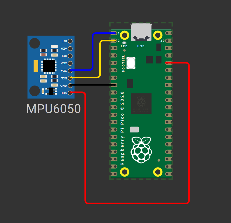
fig-Connection Diagram
⚠️ Power Note
While MPU6050 supports 5V input, use 3.3V from Pico to ensure logic-level compatibility and avoid potential I2C communication issues.
 Code
Code
Required Libraries: imu.py and vector3d.py
Before running the main script, upload these two library files to your Pico's /lib directory using Thonny IDE:
# Upload after imu.py and vector3d.py are in /lib folder

from imu import MPU6050
from time import sleep
from machine import Pin, I2C

# Initialize I2C0 on GP0 (SDA) and GP1 (SCL) at 400kHz
i2c = I2C(0, sda=Pin(0), scl=Pin(1), freq=400000)

# Create MPU6050 instance
imu = MPU6050(i2c)

print("MPU6050 initialized. Reading sensor data...")
print("ax(accel X)\tay(accel Y)\taz(accel Z)\tgx(gyro X)\tgy(gyro Y)\tgz(gyro Z)\tTemp(°C)")
print("-" * 100)

try:
    while True:
        # Read and round sensor values for clean output
        ax = round(imu.accel.x, 2)
        ay = round(imu.accel.y, 2)
        az = round(imu.accel.z, 2)
        gx = round(imu.gyro.x, 1)
        gy = round(imu.gyro.y, 1)
        gz = round(imu.gyro.z, 1)
        temp = round(imu.temperature, 2)

        # Print formatted data (carriage return for in-place update)
        print(f"{ax}\t{ay}\t{az}\t{gx}\t{gy}\t{gz}\t{temp}", end="\r")

        # Small delay to stabilize readings and reduce console spam
        sleep(0.2)

except KeyboardInterrupt:
    print("\n\nSensor reading stopped by user.")
    # Optional: Deinitialize I2C if needed for power saving
    # i2c.deinit()
# vector3d.py 3D vector class for use in inertial measurement unit drivers
# Authors Peter Hinch, Sebastian Plamauer

# V0.7 17th May 2017 pyb replaced with utime
# V0.6 18th June 2015
from utime import sleep_ms
from math import sqrt, degrees, acos, atan2


def default_wait():
    '''
    delay of 50 ms
    '''
    sleep_ms(50)


class Vector3d(object):
    '''
    Represents a vector in a 3D space using Cartesian coordinates.
    Internally uses sensor relative coordinates.
    Returns vehicle-relative x, y and z values.
    '''
    def __init__(self, transposition, scaling, update_function):
        self._vector = [0, 0, 0]
        self._ivector = [0, 0, 0]
        self.cal = (0, 0, 0)
        self.argcheck(transposition, "Transposition")
        self.argcheck(scaling, "Scaling")
        if set(transposition) != {0, 1, 2}:
            raise ValueError('Transpose indices must be unique and in range 0-2')
        self._scale = scaling
        self._transpose = transposition
        self.update = update_function

    def argcheck(self, arg, name):
        '''
        checks if arguments are of correct length
        '''
        if len(arg) != 3 or not (type(arg) is list or type(arg) is tuple):
            raise ValueError(name + ' must be a 3 element list or tuple')

    def calibrate(self, stopfunc, waitfunc=default_wait):
        '''
        calibration routine, sets cal
        '''
        self.update()
        maxvec = self._vector[:]                # Initialise max and min lists with current values
        minvec = self._vector[:]
        while not stopfunc():
            waitfunc()
            self.update()
            maxvec = list(map(max, maxvec, self._vector))
            minvec = list(map(min, minvec, self._vector))
        self.cal = tuple(map(lambda a, b: (a + b)/2, maxvec, minvec))

    @property
    def _calvector(self):
        '''
        Vector adjusted for calibration offsets
        '''
        return list(map(lambda val, offset: val - offset, self._vector, self.cal))

    @property
    def x(self):                                # Corrected, vehicle relative floating point values
        self.update()
        return self._calvector[self._transpose[0]] * self._scale[0]

    @property
    def y(self):
        self.update()
        return self._calvector[self._transpose[1]] * self._scale[1]

    @property
    def z(self):
        self.update()
        return self._calvector[self._transpose[2]] * self._scale[2]

    @property
    def xyz(self):
        self.update()
        return (self._calvector[self._transpose[0]] * self._scale[0],
                self._calvector[self._transpose[1]] * self._scale[1],
                self._calvector[self._transpose[2]] * self._scale[2])

    @property
    def magnitude(self):
        x, y, z = self.xyz  # All measurements must correspond to the same instant
        return sqrt(x**2 + y**2 + z**2)

    @property
    def inclination(self):
        x, y, z = self.xyz
        return degrees(acos(z / sqrt(x**2 + y**2 + z**2)))

    @property
    def elevation(self):
        return 90 - self.inclination

    @property
    def azimuth(self):
        x, y, z = self.xyz
        return degrees(atan2(y, x))

    # Raw uncorrected integer values from sensor
    @property
    def ix(self):
        return self._ivector[0]

    @property
    def iy(self):
        return self._ivector[1]

    @property
    def iz(self):
        return self._ivector[2]

    @property
    def ixyz(self):
        return self._ivector

    @property
    def transpose(self):
        return tuple(self._transpose)

    @property
    def scale(self):
        return tuple(self._scale)
# imu.py MicroPython driver for the InvenSense inertial measurement units
# This is the base class
# Adapted from Sebastian Plamauer's MPU9150 driver:
# https://github.com/micropython-IMU/micropython-mpu9150.git
# Authors Peter Hinch, Sebastian Plamauer
# V0.2 17th May 2017 Platform independent: utime and machine replace pyb
from utime import sleep_ms
from machine import I2C
from vector3d import Vector3d


class MPUException(OSError):
    """
    Exception for MPU devices
    """

    pass


def bytes_toint(msb, lsb):
    """
    Convert two bytes to signed integer (big endian)
    for little endian reverse msb, lsb arguments
    Can be used in an interrupt handler
    """
    if not msb & 0x80:
        return msb << 8 | lsb  # +ve
    return -(((msb ^ 255) << 8) | (lsb ^ 255) + 1)


class MPU6050(object):
    """
    Module for InvenSense IMUs. Base class implements MPU6050 6DOF sensor, with
    features common to MPU9150 and MPU9250 9DOF sensors.
    """

    _I2Cerror = "I2C failure when communicating with IMU"
    _mpu_addr = (104, 105)  # addresses of MPU9150/MPU6050. There can be two devices
    _chip_id = 104

    def __init__(self, side_str, device_addr=None, transposition=(0, 1, 2), scaling=(1, 1, 1)):

        self._accel = Vector3d(transposition, scaling, self._accel_callback)
        self._gyro = Vector3d(transposition, scaling, self._gyro_callback)
        self.buf1 = bytearray(1)  # Pre-allocated buffers for reads: allows reads to
        self.buf2 = bytearray(2)  # be done in interrupt handlers
        self.buf3 = bytearray(3)
        self.buf6 = bytearray(6)

        sleep_ms(200)  # Ensure PSU and device have settled
        if isinstance(side_str, str):  # Non-pyb targets may use other than X or Y
            self._mpu_i2c = I2C(side_str)
        elif hasattr(side_str, "readfrom"):  # Soft or hard I2C instance. See issue #3097
            self._mpu_i2c = side_str
        else:
            raise ValueError("Invalid I2C instance")

        if device_addr is None:
            devices = set(self._mpu_i2c.scan())
            mpus = devices.intersection(set(self._mpu_addr))
            number_of_mpus = len(mpus)
            if number_of_mpus == 0:
                raise MPUException("No MPU's detected")
            elif number_of_mpus == 1:
                self.mpu_addr = mpus.pop()
            else:
                raise ValueError("Two MPU's detected: must specify a device address")
        else:
            if device_addr not in (0, 1):
                raise ValueError("Device address must be 0 or 1")
            self.mpu_addr = self._mpu_addr[device_addr]

        self.chip_id  # Test communication by reading chip_id: throws exception on error
        # Can communicate with chip. Set it up.
        self.wake()  # wake it up
        self.passthrough = True  # Enable mag access from main I2C bus
        self.accel_range = 0  # default to highest sensitivity
        self.gyro_range = 0  # Likewise for gyro

    # read from device
    def _read(
        self, buf, memaddr, addr
    ):  # addr = I2C device address, memaddr = memory location within the I2C device
        """
        Read bytes to pre-allocated buffer Caller traps OSError.
        """
        self._mpu_i2c.readfrom_mem_into(addr, memaddr, buf)

    # write to device
    def _write(self, data, memaddr, addr):
        """
        Perform a memory write. Caller should trap OSError.
        """
        self.buf1[0] = data
        self._mpu_i2c.writeto_mem(addr, memaddr, self.buf1)

    # wake
    def wake(self):
        """
        Wakes the device.
        """
        try:
            self._write(0x01, 0x6B, self.mpu_addr)  # Use best clock source
        except OSError:
            raise MPUException(self._I2Cerror)
        return "awake"

    # mode
    def sleep(self):
        """
        Sets the device to sleep mode.
        """
        try:
            self._write(0x40, 0x6B, self.mpu_addr)
        except OSError:
            raise MPUException(self._I2Cerror)
        return "asleep"

    # chip_id
    @property
    def chip_id(self):
        """
        Returns Chip ID
        """
        try:
            self._read(self.buf1, 0x75, self.mpu_addr)
        except OSError:
            raise MPUException(self._I2Cerror)
        chip_id = int(self.buf1[0])
        if chip_id != self._chip_id:
            print(f"Unexpected chip ID: 0x{chip_id:02x}. Possible clone chip?")
        return chip_id

    @property
    def sensors(self):
        """
        returns sensor objects accel, gyro
        """
        return self._accel, self._gyro

    # get temperature
    @property
    def temperature(self):
        """
        Returns the temperature in degree C.
        """
        try:
            self._read(self.buf2, 0x41, self.mpu_addr)
        except OSError:
            raise MPUException(self._I2Cerror)
        # MPU-6000 and MPU-6050 Register Map and Descriptions Revision 4.2:
        return bytes_toint(self.buf2[0], self.buf2[1]) / 340 + 36.53

    # passthrough
    @property
    def passthrough(self):
        """
        Returns passthrough mode True or False
        """
        try:
            self._read(self.buf1, 0x37, self.mpu_addr)
            return self.buf1[0] & 0x02 > 0
        except OSError:
            raise MPUException(self._I2Cerror)

    @passthrough.setter
    def passthrough(self, mode):
        """
        Sets passthrough mode True or False
        """
        if type(mode) is bool:
            val = 2 if mode else 0
            try:
                self._write(val, 0x37, self.mpu_addr)  # I think this is right.
                self._write(0x00, 0x6A, self.mpu_addr)
            except OSError:
                raise MPUException(self._I2Cerror)
        else:
            raise ValueError("pass either True or False")

    # sample rate. Not sure why you'd ever want to reduce this from the default.
    @property
    def sample_rate(self):
        """
        Get sample rate as per Register Map document section 4.4
        SAMPLE_RATE= Internal_Sample_Rate / (1 + rate)
        default rate is zero i.e. sample at internal rate.
        """
        try:
            self._read(self.buf1, 0x19, self.mpu_addr)
            return self.buf1[0]
        except OSError:
            raise MPUException(self._I2Cerror)

    @sample_rate.setter
    def sample_rate(self, rate):
        """
        Set sample rate as per Register Map document section 4.4
        """
        if rate < 0 or rate > 255:
            raise ValueError("Rate must be in range 0-255")
        try:
            self._write(rate, 0x19, self.mpu_addr)
        except OSError:
            raise MPUException(self._I2Cerror)

    # Low pass filters. Using the filter_range property of the MPU9250 is
    # harmless but gyro_filter_range is preferred and offers an extra setting.
    @property
    def filter_range(self):
        """
        Returns the gyro and temperature sensor low pass filter cutoff frequency
        Pass:               0   1   2   3   4   5   6
        Cutoff (Hz):        250 184 92  41  20  10  5
        Sample rate (KHz):  8   1   1   1   1   1   1
        """
        try:
            self._read(self.buf1, 0x1A, self.mpu_addr)
            res = self.buf1[0] & 7
        except OSError:
            raise MPUException(self._I2Cerror)
        return res

    @filter_range.setter
    def filter_range(self, filt):
        """
        Sets the gyro and temperature sensor low pass filter cutoff frequency
        Pass:               0   1   2   3   4   5   6
        Cutoff (Hz):        250 184 92  41  20  10  5
        Sample rate (KHz):  8   1   1   1   1   1   1
        """
        # set range
        if filt in range(7):
            try:
                self._write(filt, 0x1A, self.mpu_addr)
            except OSError:
                raise MPUException(self._I2Cerror)
        else:
            raise ValueError("Filter coefficient must be between 0 and 6")

    # accelerometer range
    @property
    def accel_range(self):
        """
        Accelerometer range
        Value:              0   1   2   3
        for range +/-:      2   4   8   16  g
        """
        try:
            self._read(self.buf1, 0x1C, self.mpu_addr)
            ari = self.buf1[0] // 8
        except OSError:
            raise MPUException(self._I2Cerror)
        return ari

    @accel_range.setter
    def accel_range(self, accel_range):
        """
        Set accelerometer range
        Pass:               0   1   2   3
        for range +/-:      2   4   8   16  g
        """
        ar_bytes = (0x00, 0x08, 0x10, 0x18)
        if accel_range in range(len(ar_bytes)):
            try:
                self._write(ar_bytes[accel_range], 0x1C, self.mpu_addr)
            except OSError:
                raise MPUException(self._I2Cerror)
        else:
            raise ValueError("accel_range can only be 0, 1, 2 or 3")

    # gyroscope range
    @property
    def gyro_range(self):
        """
        Gyroscope range
        Value:              0   1   2    3
        for range +/-:      250 500 1000 2000  degrees/second
        """
        # set range
        try:
            self._read(self.buf1, 0x1B, self.mpu_addr)
            gri = self.buf1[0] // 8
        except OSError:
            raise MPUException(self._I2Cerror)
        return gri

    @gyro_range.setter
    def gyro_range(self, gyro_range):
        """
        Set gyroscope range
        Pass:               0   1   2    3
        for range +/-:      250 500 1000 2000  degrees/second
        """
        gr_bytes = (0x00, 0x08, 0x10, 0x18)
        if gyro_range in range(len(gr_bytes)):
            try:
                self._write(
                    gr_bytes[gyro_range], 0x1B, self.mpu_addr
                )  # Sets fchoice = b11 which enables filter
            except OSError:
                raise MPUException(self._I2Cerror)
        else:
            raise ValueError("gyro_range can only be 0, 1, 2 or 3")

    # Accelerometer
    @property
    def accel(self):
        """
        Acceleremoter object
        """
        return self._accel

    def _accel_callback(self):
        """
        Update accelerometer Vector3d object
        """
        try:
            self._read(self.buf6, 0x3B, self.mpu_addr)
        except OSError:
            raise MPUException(self._I2Cerror)
        self._accel._ivector[0] = bytes_toint(self.buf6[0], self.buf6[1])
        self._accel._ivector[1] = bytes_toint(self.buf6[2], self.buf6[3])
        self._accel._ivector[2] = bytes_toint(self.buf6[4], self.buf6[5])
        scale = (16384, 8192, 4096, 2048)
        self._accel._vector[0] = self._accel._ivector[0] / scale[self.accel_range]
        self._accel._vector[1] = self._accel._ivector[1] / scale[self.accel_range]
        self._accel._vector[2] = self._accel._ivector[2] / scale[self.accel_range]

    def get_accel_irq(self):
        """
        For use in interrupt handlers. Sets self._accel._ivector[] to signed
        unscaled integer accelerometer values
        """
        self._read(self.buf6, 0x3B, self.mpu_addr)
        self._accel._ivector[0] = bytes_toint(self.buf6[0], self.buf6[1])
        self._accel._ivector[1] = bytes_toint(self.buf6[2], self.buf6[3])
        self._accel._ivector[2] = bytes_toint(self.buf6[4], self.buf6[5])

    # Gyro
    @property
    def gyro(self):
        """
        Gyroscope object
        """
        return self._gyro

    def _gyro_callback(self):
        """
        Update gyroscope Vector3d object
        """
        try:
            self._read(self.buf6, 0x43, self.mpu_addr)
        except OSError:
            raise MPUException(self._I2Cerror)
        self._gyro._ivector[0] = bytes_toint(self.buf6[0], self.buf6[1])
        self._gyro._ivector[1] = bytes_toint(self.buf6[2], self.buf6[3])
        self._gyro._ivector[2] = bytes_toint(self.buf6[4], self.buf6[5])
        scale = (131, 65.5, 32.8, 16.4)
        self._gyro._vector[0] = self._gyro._ivector[0] / scale[self.gyro_range]
        self._gyro._vector[1] = self._gyro._ivector[1] / scale[self.gyro_range]
        self._gyro._vector[2] = self._gyro._ivector[2] / scale[self.gyro_range]

    def get_gyro_irq(self):
        """
        For use in interrupt handlers. Sets self._gyro._ivector[] to signed
        unscaled integer gyro values. Error trapping disallowed.
        """
        self._read(self.buf6, 0x43, self.mpu_addr)
        self._gyro._ivector[0] = bytes_toint(self.buf6[0], self.buf6[1])
        self._gyro._ivector[1] = bytes_toint(self.buf6[2], self.buf6[3])
        self._gyro._ivector[2] = bytes_toint(self.buf6[4], self.buf6[5])
Code Explanation
 Library Imports
from imu import MPU6050      # Custom MPU6050 driver class
from time import sleep        # For timing delays between reads
from machine import Pin, I2C  # MicroPython hardware abstraction
machine.I2C: Configures hardware I2C peripheral on the RP2040machine.Pin: Assigns GPIO pins for SDA/SCL signals
I2C Initialization
| Parameter | Value | Meaning |
|---|---|---|
0 |
I2C port ID | Selects I2C0 controller (use 1 for I2C1) |
sda=Pin(0) |
GPIO 0 | Data line pin assignment |
scl=Pin(1) |
GPIO 1 | Clock line pin assignment |
freq=400000 |
400 kHz | Fast-mode I2C speed for responsive reads |
MPU6050 Object Creation
- Instantiates the sensor driver with the configured I2C bus
- Automatically wakes the MPU6050 from sleep mode via
PWR_MGMT_1register
Data Reading Loop
ax = round(imu.accel.x, 2)  # X-axis acceleration in m/s²
gx = round(imu.gyro.x, 1)   # X-axis rotation in °/s
temp = round(imu.temperature, 2)  # Chip temperature in °C
- Properties
accel,gyro, andtemperaturetrigger I2C register reads - Values are scaled from raw 16-bit integers to physical units
round()improves readability in the console output
Output Formatting
\t(tab) aligns columns in the Thonny shellend="\r"returns cursor to line start for real-time value updates- Press
Ctrl+Cto stop execution gracefully
Simulation
Not able to view the simulation
- Desktop or Laptop : Reload this page ( Ctrl+R )
- Mobile : Use Landscape Mode and reload the page
Raspberry Pi Pico, Arduino, sensors, and IoT maker essential Kits—perfectly matched for your learning.


🛑 Troubleshooting (Common Issues & Fixes)
❌ Issue 1: OSError: [Errno 121] EIO or "No device at address 0x68"
✅ Causes: - Incorrect I2C pin assignment or wiring - MPU6050 not powered or AD0 pin floating - I2C pull-up resistors missing (some modules lack onboard resistors)
✅ Fix:
# Run I2C scanner to verify device detection
from machine import I2C, Pin
i2c = I2C(0, sda=Pin(0), scl=Pin(1))
print("Scanning I2C bus...")
devices = i2c.scan()
print("Found devices:", [hex(addr) for addr in devices])
0x69 – update code accordingly
❌ Issue 2: Sensor readings are noisy or unstable
✅ Causes: - Mechanical vibrations or loose mounting - Insufficient sampling delay - Unfiltered raw data
✅ Fix:
# Add simple moving average filter (example for 5 samples)
def read_filtered(sensor_prop, samples=5):
    values = [getattr(sensor_prop, axis) for axis in ['x','y','z'] for _ in range(samples)]
    return [sum(values[i::3])/samples for i in range(3)]

# Usage in loop:
ax, ay, az = read_filtered(imu.accel)
sleep() delay to 0.5s for slower, stable reads
- Consider using the onboard DMP for sensor fusion (advanced)
❌ Issue 3: Accelerometer Z-axis reads ~0 instead of ~9.8 when flat
✅ Causes: - Sensor orientation misunderstanding - Calibration offset required - Wrong full-scale range configuration
✅ Fix:
# Verify orientation: Z-axis should read +9.8 m/s² when board faces up
# If inverted, apply sign correction:
az = -imu.accel.z  # Flip sign if needed

# For calibration: collect 100 stationary samples and compute offset
# Then subtract offset from future readings
❌ Issue 4: Pico resets or behaves erratically during reads
✅ Causes: - I2C bus contention or clock stretching issues - Power supply instability - Library compatibility with MicroPython version
✅ Fix:
- Add 0.1µF ceramic capacitor between MPU6050 VCC and GND
- Use freq=100000 (100kHz) instead of 400kHz for more reliable communication
- Update to latest MicroPython firmware: Download here
🏁 Conclusion
We have successfully interfaced an MPU6050 6-DoF IMU sensor with a Raspberry Pi Pico using MicroPython 🎉. We now understand:
- How I2C communication enables digital sensor interfacing
- How to read and interpret accelerometer (m/s²) and gyroscope (°/s) data
- Best practices for wiring, library management, and troubleshooting
With this foundation, you can build advanced projects like: - 🤖 Self-balancing robots and inverted pendulums - 🚁 Drone flight stabilization systems - 🎮 Motion-controlled gaming interfaces - 📊 Vibration monitoring for predictive maintenance - 🧭 Tilt-compensated compass systems (with added magnetometer)
Next Steps
- Calibrate your sensor: Implement offset correction for zero-g and zero-rate conditions
- Fuse sensor data: Use complementary filters or Kalman filters to combine accel + gyro for stable orientation
- Add visualization: Stream data to Thonny plotter, MQTT dashboard, or OLED display
- Explore DMP: Leverage the MPU6050's onboard Digital Motion Processor for quaternion output (requires advanced library)
📚 Further Reading: - MPU6050 Register Map (InvenSense) - MicroPython I2C Documentation - RP2040 Datasheet - I2C Peripheral
Extras
Components details
- Raspberry Pi Pico / Pico 2 : Pin Diagram
- Raspberry Pi Pico : Data Sheet
- Raspberry Pi Pico 2 : Data Sheet
- Raspberry Pi Pico W : Data Sheet
- Raspberry Pi Pico 2 W : Data Sheet
- MPU6050 : Datasheet
Library Sources
imu.py&vector3d.py: micropython-IMU GitHub Repository- Alternative lightweight driver: TimHanewich/MPU6050-MicroPython
Quick Reference: MPU6050 Register Map
| Register | Address | Purpose |
|---|---|---|
WHO_AM_I |
0x75 |
Device ID verification (should return 0x68) |
PWR_MGMT_1 |
0x6B |
Power management & wake-up control |
ACCEL_XOUT_H |
0x3B |
Start of 14-bit accelerometer data block |
GYRO_XOUT_H |
0x43 |
Start of 14-bit gyroscope data block |
TEMP_OUT_H |
0x41 |
Temperature sensor output |
🔐 Pro Tip
Always read WHO_AM_I register during initialization to confirm successful I2C communication before proceeding with sensor reads.