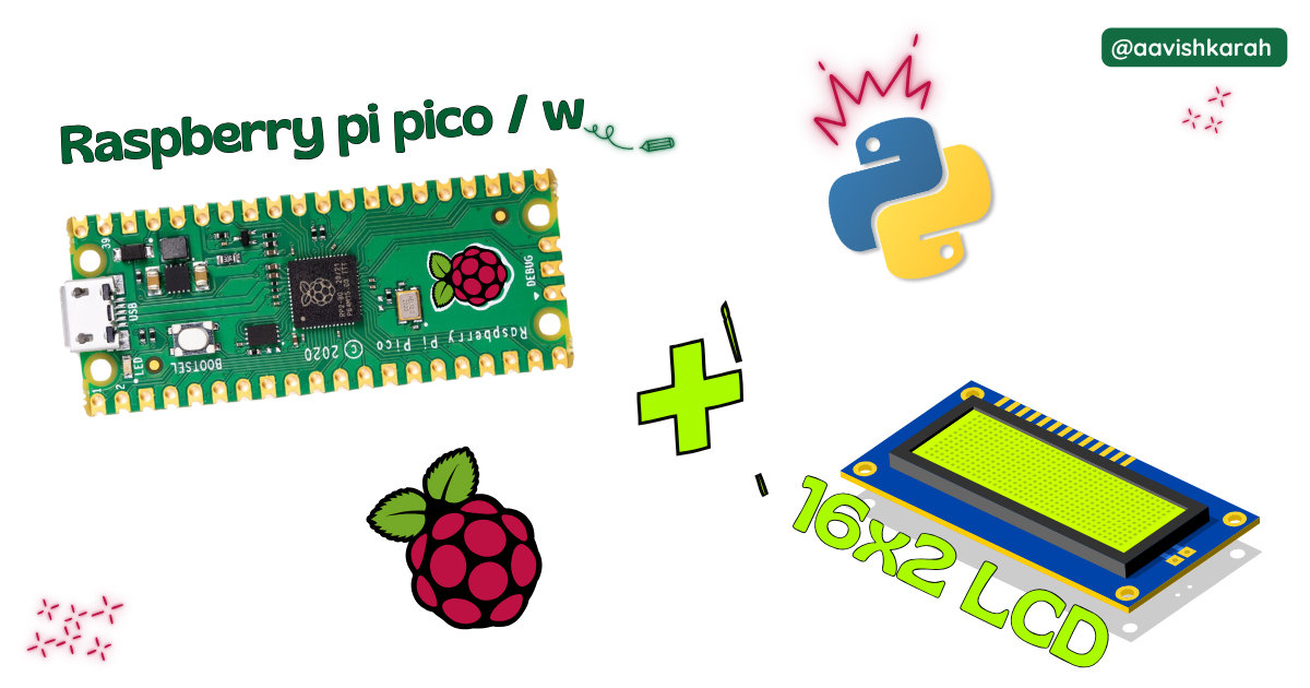
Interfacing 16x2 LCD display with Raspberry Pi Pico & MicroPython

Table of Contents
Abstract
In this article, a comprehensive step-by-step guide to interface 16x2 LCD display with Raspberry Pi Pico board using MicroPython. Raspberry Pi Pico has 4 different variants (Pico, Pico 2, Pico W, Pico 2W) supporting micro-python. This articles lays the foundation for more advanced embedded system and IoT projects.
 Pre-Request
- OS : Windows / Linux / Mac / Chrome
- Thonny IDE.
- MicroPython firmware in Raspberry Pi Pico / Pico 2 / Pico W / Pico 2W.
- For step by step procedure click here .
Hardware Required
- Raspberry Pi Pico / Pico 2 / Pico W / Pico 2W.
- 16x2 LCD.
- Potentiometer (POT)
- Resistor.
- BreadBoard.
- Micro USB Cable.
- Connecting wires.
- 5V DC power supply (Optional)
| Components | Purchase Link |
|---|---|
| Raspberry Pi Pico | link |
| Raspberry Pi Pico 2 | link |
| Raspberry Pi Pico W | link |
| Raspberry Pi Pico 2W | link |
| 16x2 LCD | link |
| Potentiometer (POT) | link |
| BreadBoard | large : small |
| Connecting Wires | link |
| Micro USB Cable | link |
| 5V DC Adaptor | link |
Don't own a hardware
No worries,
Still you can learn using simulation.
check out simulation part 
Connection Table
16x2 LCD can be connected in 4 wire and 8 wire mode. In this article 4 wire mode is demonstrated, as 8 wire mode is rarely used now a days.
Info
With I2C LCD interface, we can interface 16x2 LCD display in 2 wire mode. click here to know how to interface 16x2 LCD display in serial mode using 2 wire system.
| 16x2 LCD | GPIO | Remarks |
|---|---|---|
| VSS (1) | GND | Ground |
| VCC (2) | +5 V | +5V of Board or External 5V DC Supply |
| VEE (3) | -- | POT variable terminal as shown in circuit |
| RS (4) | 15 | Register Select Pin |
| RW (5) | GND | Read / Write Pin |
| E (6) | 14 | Enable Pin |
| D0 to D3 | -- | No connection (∵ 4 wire mode) |
| D4 (11) | 13 | Data line 4 |
| D5 (12) | 12 | Data line 5 |
| D6 (13) | 11 | Data line 6 |
| D7 (14) | 10 | Data line 7 |
| A (15) | -- | +5V of Board or External 5V DC Supply |
| K (16) | -- | Ground through Resistor |
Note
- To control the backlight led programmatically. LCD Pin A(15) can be connected to GPIO.
- VCC (2) can be connected to external +5 V DC supply or to the VBUS pin number 40 of Raspberry Pi Pico Board.
- While using External 5 V supply for 16x2 LCD, make sure ground pin of External Supply and Pico board is connected.

fig-Connection Diagram
 Code
Code
Code Explanation

timemodule for creating delay.lcd_apimodule for interacting with 16x2 lcd display hardware.

- Creating the instance of LCD_16x2_parallel object.
- Depending upon your connection, change the GPIO pin numbers.
- (rs, e, d4, d5, d6, d7)
- As per the above connection table
LCD_16x2_parallel(15, 14, 13, 12, 11, 10)

lcd.returnHome()method sets the display cursor to Row 1 and Column 1- The content to be displayed is passed to
lcd.display()method.Make sure, the content is less than or equal to 16 Characters.
- A delay of 2 seconds is given, so that the user can view the content before new content is displayed.

- Each row can display 16 characters.
- To continue the display content, we need to set the cursor to Row 2, Column 1
- Setting of cursor to Row 2 and Column 1 is achieved by
lcd.setCursor(2,0)method. - As discussed in the previous code section, display method takes the data to be displayed on the LCD screen.
- To have a Typewriting effect, 2nd argument of delay in milli seconds can be passed.
- In line 16, a delay of 100 ms is passed.
- This adds a delay of 100 ms delay between the display of the letters.
- Clearing1 the screen to display the new data is achieved by
lcd.clearScreen()method.- Using
clearScreenmethod also brings the cursor to the starting position (Row 1 and Column 1)
- Using
Try It
- Alter the output content on the display by passing your data argument to the
displaymethod. - Observe the typing effect in the content display by altering the delay value of
display(<data>, <delay>)method.
Simulation
Not able to view the simulation
- Desktop or Laptop : Reload this page ( Ctrl+R )
- Mobile : Use Landscape Mode and reload the page
Extras
Components details
- Raspberry Pi Pico / Pico 2 : Pin Diagram
- Raspberry Pi Pico : Data Sheet
- Raspberry Pi Pico 2 : Data Sheet
- Raspberry Pi Pico W : Data Sheet
- Raspberry Pi Pico 2 W : Data Sheet
Modules / Libraries Used
- time
timemodule provides functions related to date & time, measuring time intervals and generating delays.- More Details
- lcd_api
- To interact with 16x2 LCD display.
- It is a third part library or user defined library.
